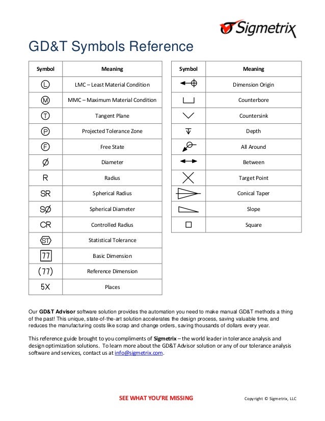
Gd And T Symbols Definitions

Actualx true x 2 actual y true y 2.
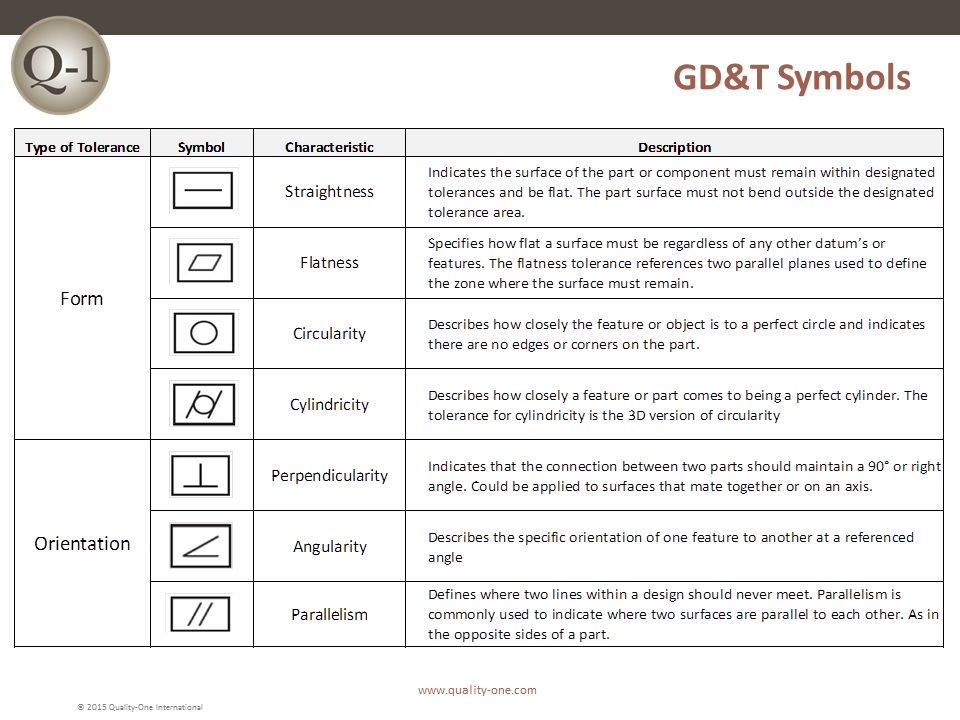
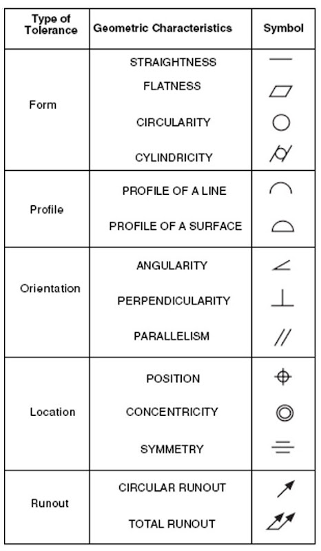
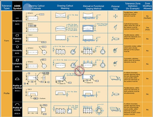
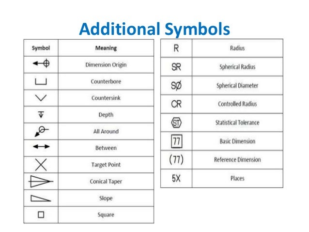
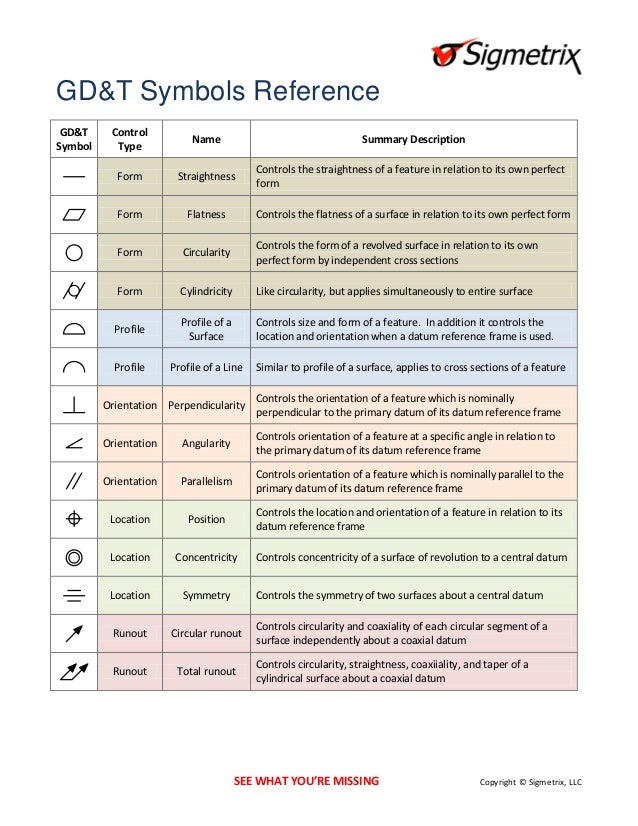
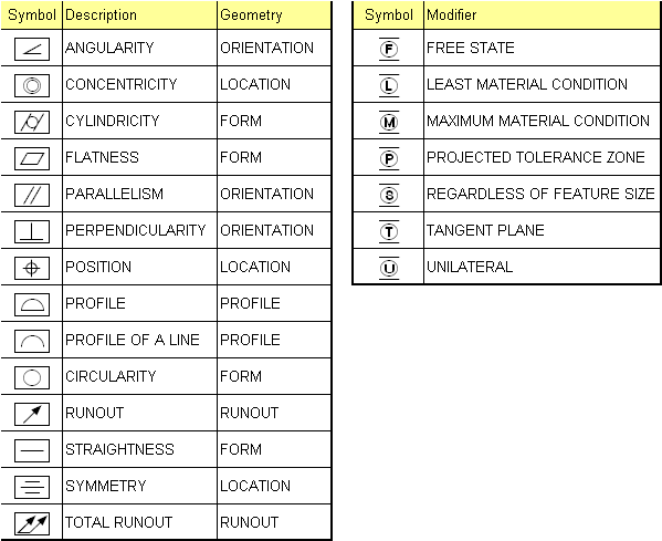
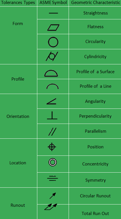
Gd and t symbols definitions. Designers and engineers utilize this international language on their drawings to accurately describe part features on the basis of size form orientation and location. Yes mmc or lmc applicable. Geometric dimensioning tolerancing gd t sometimes refered to as gdt is a set of standard symbols which are used to define parts and assembly features and their tolerance zones in dimensioning engineering drawings. The symbolic language in gd t describes the geometry and allowable variation or error it can specify the requirements of accuracy and precision of the cnc machining parts.
Also it defines a part based on how it functions. Gd t symmetry is a 3 dimensional tolerance that is used to ensure that two features on a part are uniform across a datum plane. In geometric dimensioning and tolerancing gd t a unique set of gd t symbols are used to define the relationships between part features and measurement references. Do you know all of the gd t symbols definitions.
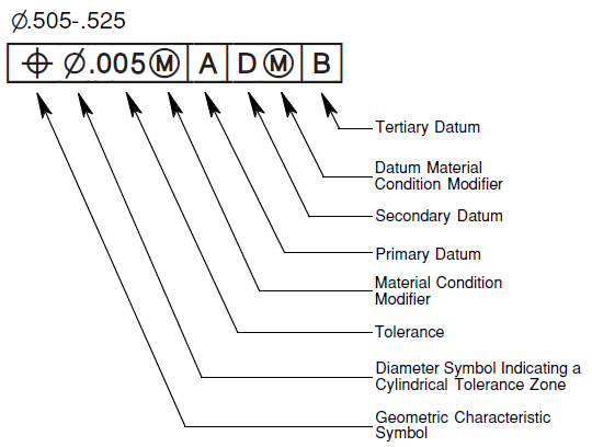
This formula must be less than the ø true position tolerance. Gauge pin inserted perpendicular to datum pin gauge ø 9 92 9 95 0 03 pin gauge od m 0 03 part actual position true center measure x and y location and compare to the true position. Gd t aims to communicate the design intent in a way that the desired form fit function and interchangeability of feature is conveyed on the drawings without confusion.

